ビットエラーレートテスタ “BERT1000シリーズ” PXI
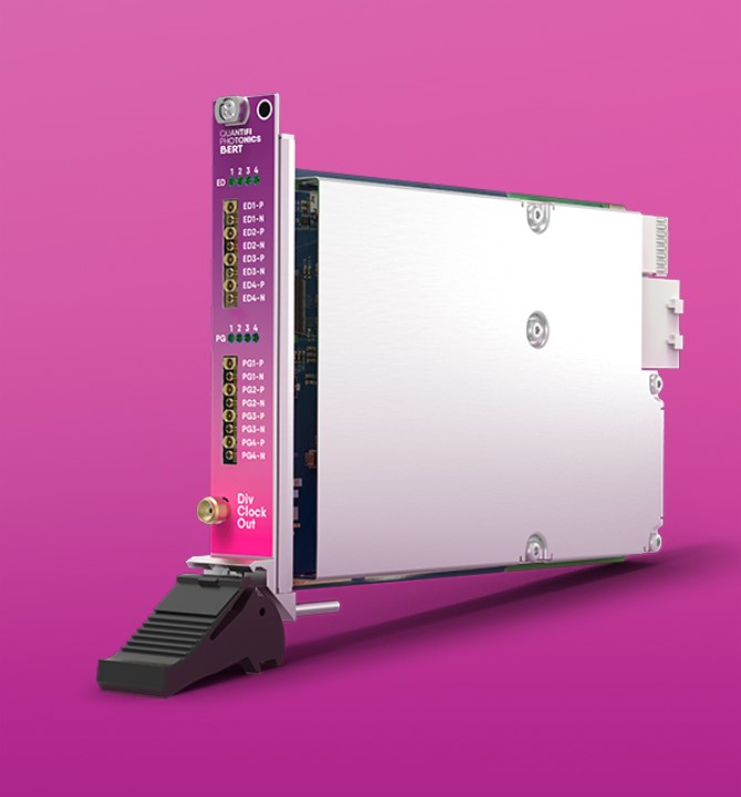 BERT 1000 シリーズ (ビットエラーレートテスタ) PXIは最大30 Gb/sのデータレートにおける光トランシーバおよび光電気部品の設計、特性評価、製造に使用される2または4チャネルのパルスパターン発生器(PPG)およびエラー検出器です。拡張性と卓越した信号忠実度により、400 Gb/s通信エコシステム向けのコスト効率の高いテストソリューションです。
プログラマブル・ディエンファシスとCTLEプロセッサ
プログラム可能なPPG Txディエンファシスとエラー検出器レシーバ連続時間線形イコライザ(CTLE)により、有限の同軸ケーブル相互接続損失を補償することができます。
クロックリカバリ内蔵
統合CDRでの4チャネル同時テストにより、BERTは多用途で使いやすい機器となります。クロックリカバリのハードウェアを追加する必要はありません。
内蔵クロックシンセサイザ
クロックシンセサイザーを内蔵し、利便性と操作性を向上させました。
シングル・プラットフォーム・テスト
1つのプラットフォームですべてのDUTの特性評価を行うことができるため、測定器間でケーブルやパッチコードを切り替える時間を短縮できます。
PXIシステムでの高いチャネル密度
1スロットのPXIeモジュールあたり最大4チャネルで、1つのPXIeメインフレームあたり最大68の同期チャネルにフィットします。
直感的なGUIによるシンプルな制御
使いやすいGUIにより、時間を節約し、複雑さを軽減します。シングルパネル・インターフェースからすべてのチャネルと機能を制御できます。
アプリケーション事例
- 30Gbps対応マルチチャネルBERテスタ
- アクティブ光ケーブル試験
- 高速SerDesの特性評価
仕様
| General Specifications | PXI |
|---|---|
| Bus connection | PXIe |
| Slot count | 1 |
| Dimensions (HxWxD) | 130 x 20 x 215 mm |
| Weight | ~ 250 grams |
| Operating temperature range | 5 °C to 45 °C |
| Storage temperature range | -40 °C to 70 °C |
| Power Specifications | PXI |
|---|---|
| AC input voltage range | Please refer to the latest PXI Express Hardware Specifications published by the PXI Systems Alliance. |
| AC input current | |
| AC frequency range | |
| DC output voltage | |
| DC output current max | |
| Dimensions (LxWxH) |
| Model Number | PXI 1005 |
|---|---|
| Number of channels | 4 |
| RF output | Differential |
| RF connector | 2 x breakout cables with 8 x SMA connectors |
| Impedance | 100 ohms between differential outputs |
| Data coding | NRZ |
| Data rate | 1.25 to 14.50 Gbps |
| Data rate step size | 2 kbps |
| PRBS patterns | 2n-1, n = 9, 15 or 31 |
| Output amplitude (mV differential) | Adjustable 250 to 1100 |
| Output amplitude steps (mV differential) | 5 |
| Rise/fall time (20% to 80%) | < 18 ps |
| Intrinsic jitter | < 850 fs rms (typical) |
| Crossing point adjustment | 40% to 60% |
| Programmable de-emphasis | 2 pre taps, 1 post tap |
| Polarity inversion | Yes |
| Divided Clock Output | 1005 |
|---|---|
| Rf output | Single-ended SMA |
| Impedance | 50 ohms |
| Frequency | 100 – 156.25 MHz Programmable Synthesizer Reference Out |
| Intrinsic jitter | TBD |
| Output amplitude | 700 mV (typical) |
| Selectable clock divider | Divide by n, with n = 2,4,8 |
| Clock and Data Recovery | 1005 |
|---|---|
| Data rate | 1.25 to 14.5 Gbps |
| Loop bandwidth | Tunable 6 to 10 MHz |
| CDR output | No |
| Breakout Cables | 1005 |
|---|---|
| Length | 30 cm |
| Connectors | SMA, Male |
| Skew | < 2 ps skew match |
| Error Detector | 1005 |
|---|---|
| Number of channels | 4 |
| RF input | AC coupled differential |
| Impedance | 100 ohms between differential outputs |
| Data rate | 1.25 Gbps to 14.50 Gbps |
| Data rate step size | 2 kbps |
| PRBS patterns | 2n-1, n = 7, 9, 10, 11, 15, 23 or 31 |
| Sensitivity | 25 mV |
| Max input | 1000 mV |
| Clock source | Independent CDR on each input channel |
| Polarity inversion | Yes |
| Equalizer | Programmable linear input CTLE equalizer |
| Eye contours | 3D Eye Monitor on each input to allow advanced measurements such as BER contours and eye parameters |